
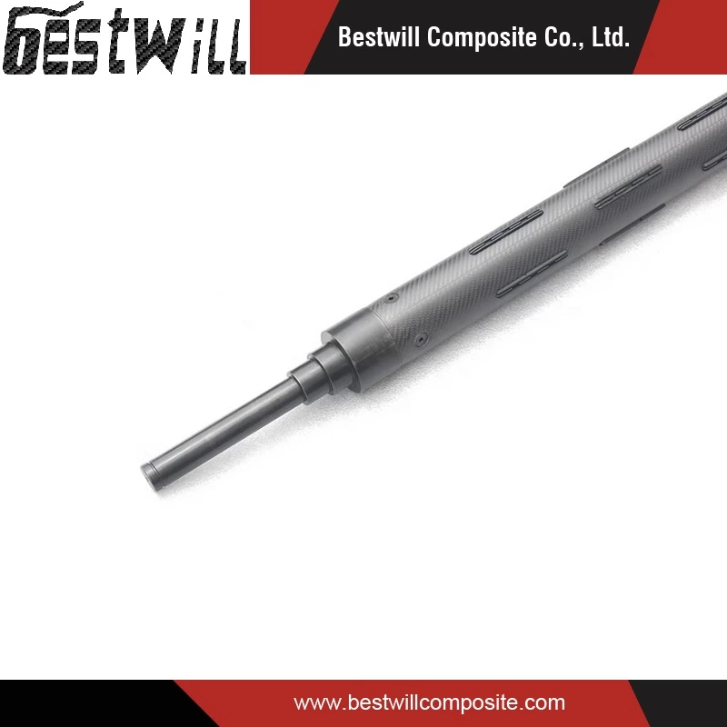
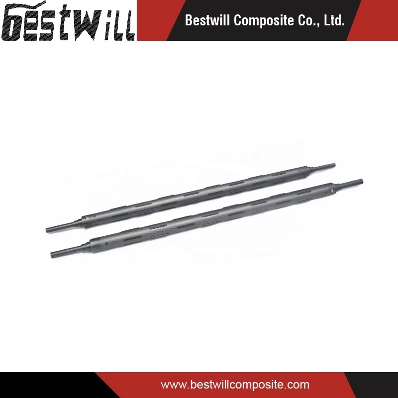
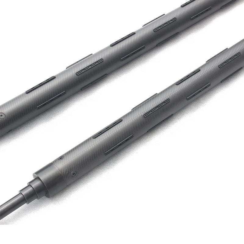
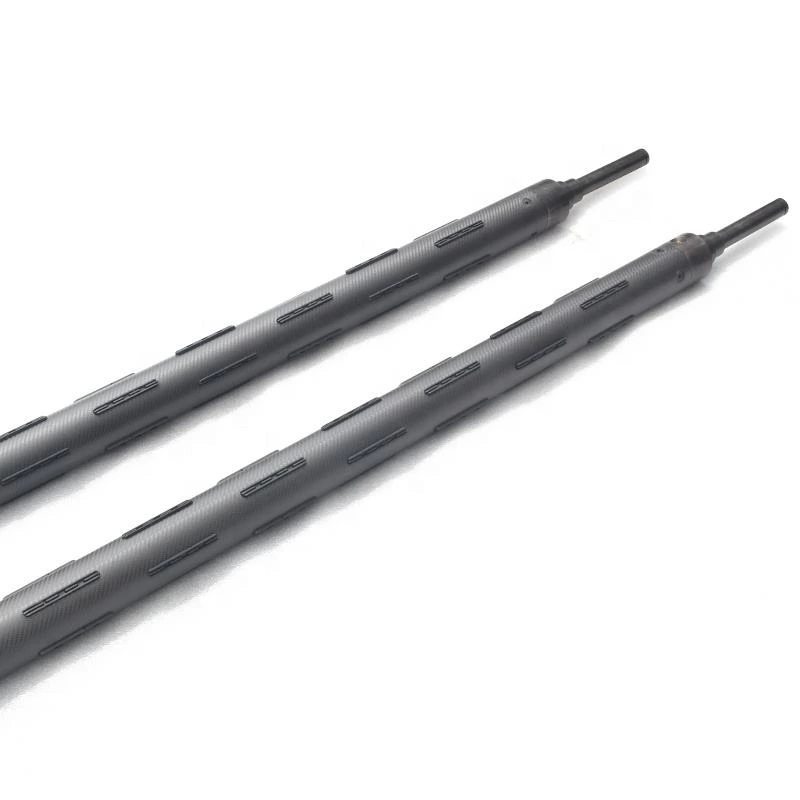
Carbon Fiber Pneumatic Expanding Air Roller
Origin: China
Brand: BEST WILL COMPOSITE
Techniques: Carbon Fiber Prepreg Roll Wrapping
Material: Carbon Fiber Prepreg + Epoxy Resin
Length: 6000mm Max
Shaft Diameter: Customized
Supply Type: Make-to-Order
Application: Industrial Winding and Rewinding Systems
Dynamic Balancing Grade: G6.3
Quality Testing: Deflection Testing & Dynamic Balancing
Product Description
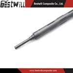
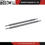
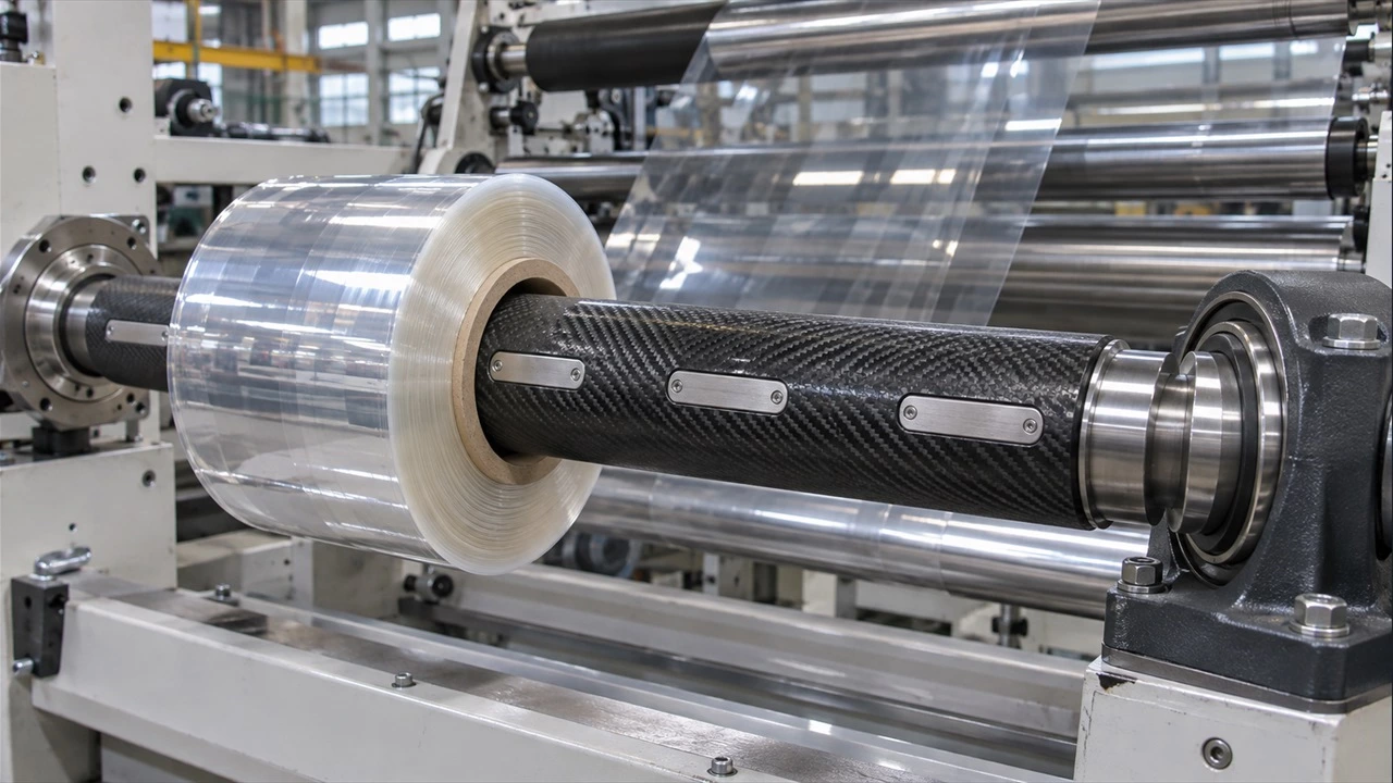
Our Carbon Fiber Pneumatic Expanding Air Roller are designed for high-performance winding and unwinding applications in printing, packaging, paper converting, plastic film processing, and other industrial roll-to-roll systems.
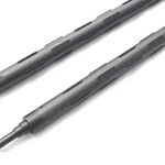
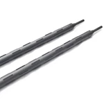
The air shaft features a lightweight carbon fiber composite tube combined with precision-machined metal shaft ends and a pneumatic expansion mechanism, providing an effective balance of low weight, structural rigidity, and reliable operation.
The carbon fiber tube is manufactured using carbon fiber prepreg roll-wrapping technology. Multiple layers of epoxy resin pre-impregnated carbon fiber are arranged in engineered fiber orientations to achieve the required bending stiffness, torsional strength, and mechanical performance.
Compared with conventional steel shafts, the lightweight composite structure can reduce handling effort, rotational inertia, and the loads associated with shaft weight, helping improve production efficiency.
We manufacture complete carbon fiber pneumatic expanding air shaft assemblies with lengths up to 6000 mm, offering customized designs to meet different industrial requirements.
Technical Specifications
| Parameter | Specification |
|---|---|
| Product Name | Carbon Fiber Pneumatic Expanding Air Shaft |
| Product Type | Complete Pneumatic Air Shaft Assembly |
| Shaft Structure | Carbon Fiber Composite Tube with Metal Shaft Ends |
| Shaft Body Material | Carbon Fiber Reinforced Polymer (CFRP) |
| Reinforcement | Carbon Fiber Prepreg |
| Resin System | Epoxy Resin |
| Manufacturing Process | Prepreg Roll Wrapping |
| Common Core Sizes | 3 inch (76.2 mm) / 6 inch (152.4 mm) |
| Reference Shaft Body Diameters | 74–75 mm / 149–150 mm |
| Maximum Manufacturing Length | 6000 mm |
| Expansion Mechanism | Pneumatic Expansion System |
| Dynamic Balancing Grade | G6.3 |
| Deflection Testing | Performed |
| Shaft End Configuration | Customized Metal Shaft Ends |
| Surface Finish | Precision Machined / Ground |
| Load Capacity | Customized According to Application |
| Operating Speed | According to Application Requirements |
| Customization | Diameter, Length, Wall Thickness, Fiber Layup and Shaft Ends |
Note: Actual load capacity, allowable deflection, operating speed, and other performance parameters depend on shaft dimensions, operating conditions, and engineering requirements.
Key Features and Advantages
1. Lightweight Construction and Easier Handling
Carbon fiber composite tubes offer a significantly lower material density than steel, making it possible to reduce shaft weight while maintaining the required structural performance.
Depending on the tube design and wall thickness, the carbon fiber tube may weigh substantially less than a comparable steel tube.
The lightweight construction provides several operational advantages:
-
Easier installation, removal, and manual handling
-
Reduced handling effort during roll changes
-
Lower rotational inertia
-
Reduced weight-related loading on bearings and supporting components
-
Improved equipment responsiveness during acceleration and deceleration
2. High Strength and Structural Rigidity
The carbon fiber prepreg composite structure offers a high strength-to-weight ratio and can be engineered for specific bending and torsional requirements.
By optimizing the fiber orientation, laminate thickness, and shaft geometry, the composite tube can provide the mechanical performance required for demanding industrial winding applications.
3. Excellent Fatigue Resistance
Carbon fiber composites can provide good fatigue performance when properly designed and manufactured.
The engineered composite structure helps maintain mechanical performance under repeated operating loads, making it suitable for industrial applications involving frequent winding, unwinding, acceleration, and deceleration cycles.
4. Fast Pneumatic Expansion and Roll Changes
The pneumatic expansion mechanism allows the shaft to securely grip the winding core when inflated and release it when deflated.
This design enables convenient roll installation and removal without dismantling the shaft-end components during normal operation.
The quick expansion and release mechanism helps reduce roll changeover time and improve production efficiency.
5. Low Rotational Inertia and Stable Operation
The reduced mass of the carbon fiber composite shaft body helps lower rotational inertia compared with heavier conventional designs.
This can improve acceleration and deceleration response while reducing the energy required to change rotational speed.
Dynamic balancing to Grade G6.3 helps control residual unbalance and supports stable rotational performance under specified operating conditions.
6. Customizable Carbon Fiber Composite Structure
The composite shaft body can be engineered with different fiber orientations, wall thicknesses, and laminate configurations.
This flexibility allows the shaft design to be optimized for specific requirements, including bending stiffness, torque transmission, weight reduction, and dimensional constraints.
Carbon Fiber Prepreg Roll-Wrapping Technology
How Are the Carbon Fiber Layers Arranged?
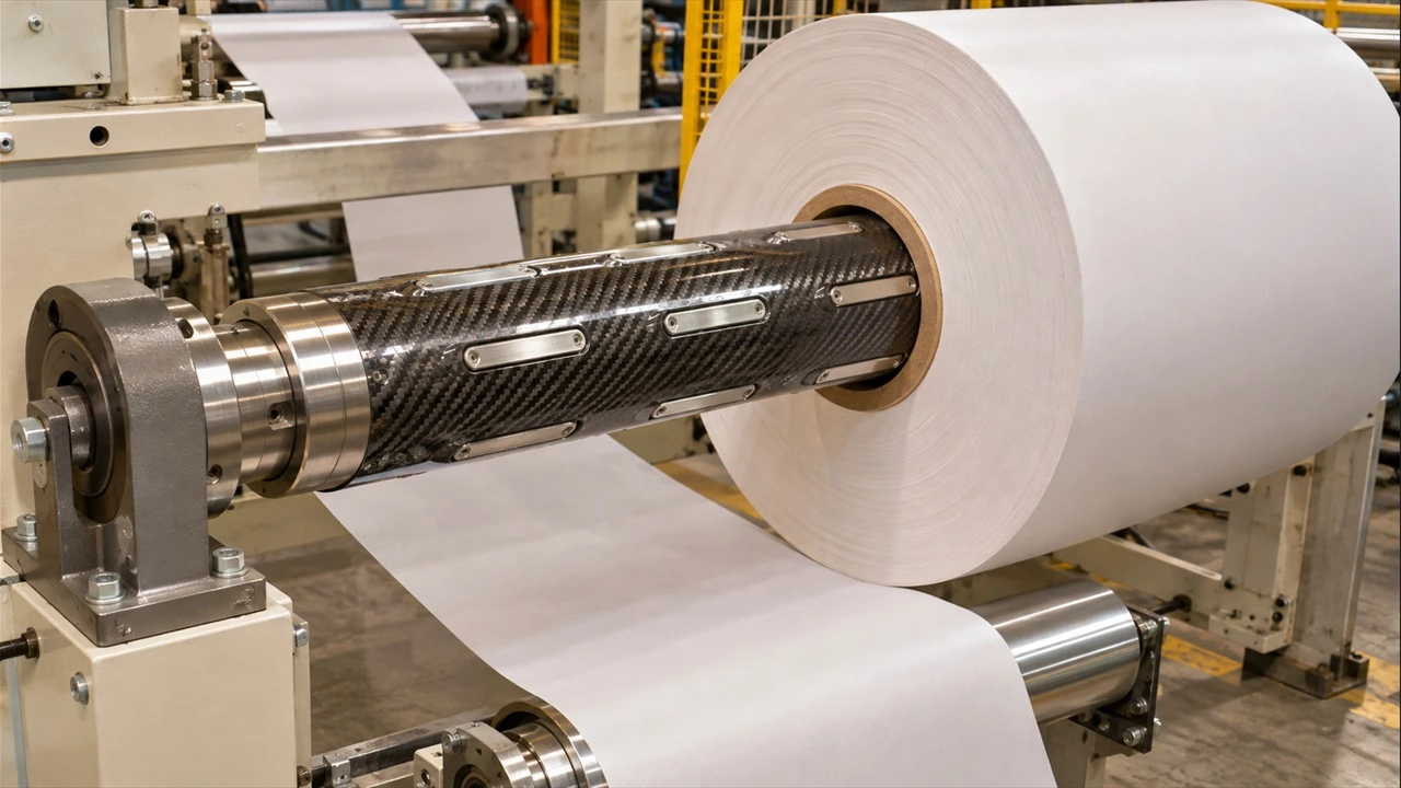
Our carbon fiber tubes are manufactured using a controlled prepreg roll-wrapping process rather than conventional filament winding.
Carbon fiber prepreg sheets are cut and arranged according to a predetermined laminate design, then wrapped around a precision mandrel to form the composite tube.
Different fiber orientations are selected to achieve specific mechanical properties:
-
0° Fiber Orientation: Primarily contributes to axial strength and bending stiffness.
-
±45° Fiber Orientation: Helps improve torsional stiffness and shear performance.
-
90° Fiber Orientation: Provides circumferential reinforcement and helps resist hoop stresses.
The combination of these fiber orientations allows the laminate structure to be tailored to different shaft applications.
After roll wrapping, the composite tube undergoes controlled curing, mandrel removal, precision machining, and surface finishing.
This manufacturing process provides flexibility in composite design and supports the production of lightweight, high-performance carbon fiber shaft tubes.
Manufacturing Process
Step 1 — Prepreg Material Preparation
Carbon fiber prepreg materials are selected and cut according to the required tube dimensions and laminate design.
Step 2 — Fiber Layup Design
The fiber orientation and number of prepreg layers are determined based on the required mechanical performance.
Step 3 — Prepreg Roll Wrapping
The prepared carbon fiber prepreg layers are wrapped around a precision mandrel to form the composite shaft body.
Step 4 — Controlled Curing
The wrapped tube is cured under controlled processing conditions to consolidate the composite structure.
Step 5 — Precision Machining
The cured carbon fiber tube is trimmed, machined, and ground to meet the specified dimensional and surface requirements.
Step 6 — Pneumatic Shaft Assembly
The carbon fiber tube is integrated with metal shaft ends and pneumatic expansion components to form a complete air shaft assembly.
Step 7 — Quality Inspection and Testing
The finished air shaft undergoes dimensional inspection, deflection testing, and dynamic balancing testing to verify compliance with the specified requirements.
Quality Control & Testing
Dimensional Inspection
Shaft dimensions, machining accuracy, and surface finish are inspected according to the approved technical drawings.
Deflection Testing
Deflection testing is performed to evaluate shaft bending behavior and structural stiffness under specified loading conditions.
This helps verify the shaft's suitability for its intended winding and unwinding application.
Dynamic Balancing — Grade G6.3
Dynamic balancing is performed to Grade G6.3 to control residual unbalance and help minimize vibration during rotation.
The balancing requirements are evaluated according to the shaft configuration and intended operating conditions.
Pneumatic Expansion Function Testing
The pneumatic expansion mechanism is checked for proper expansion, retraction, and reliable gripping performance.
Main Manufacturing Equipment
-
Carbon Fiber Prepreg Roll-Wrapping Machine
-
Composite Curing Equipment
-
Centerless Grinding Machine
-
Cylindrical Grinding Machine
-
CNC Machining Equipment
-
Deflection Testing Equipment
-
Dynamic Balancing Machine
Applications
Carbon fiber pneumatic expanding air shafts are suitable for a wide range of industrial winding and unwinding applications, including:
-
Printing and Rewinding Machines
-
Slitting and Converting Equipment
-
Flexible Packaging Machinery
-
Plastic Film Processing Equipment
-
Paper Manufacturing and Converting Machines
-
Laminating and Coating Machines
-
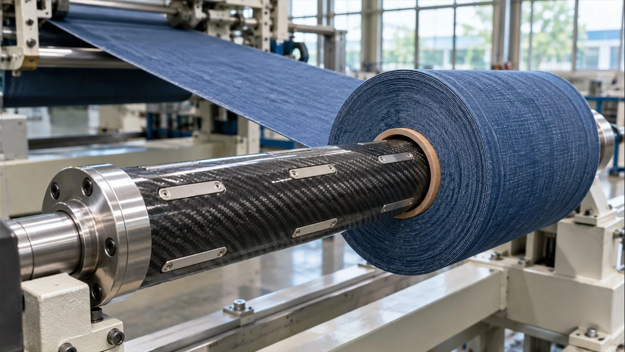
Textile and Nonwoven Processing Equipment
-
Industrial Roll Handling Systems
Custom Carbon Fiber Pneumatic Air Shaft Solutions
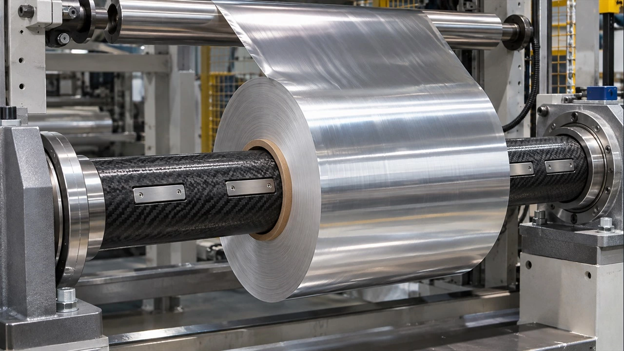
We manufacture complete carbon fiber pneumatic expanding air shaft assemblies using advanced prepreg roll-wrapping technology.
Our manufacturing capabilities include carbon fiber composite tube production, precision machining, metal shaft-end integration, pneumatic assembly, deflection testing, and G6.3 dynamic balancing.
With a maximum manufacturing length of 6000 mm, we provide customized air shaft solutions based on customer drawings and application requirements.
Customization options include shaft diameter, overall length, wall thickness, composite layup, expansion mechanism, and shaft-end configuration.
For quotations and technical recommendations, please provide the required winding core diameter, shaft dimensions, maximum roll weight, operating speed, and installation drawings.
Contact us for custom carbon fiber pneumatic expanding air shaft solutions and quotations.